

Load Cell Selection & Calibration Guide: Measuring Weight in Software
Four load cell form factors, precise force-to-voltage conversion — and the interface board is what turns microvolt signals into clean weight readings in your code. Here's how to choose and wire the right load cell setup.
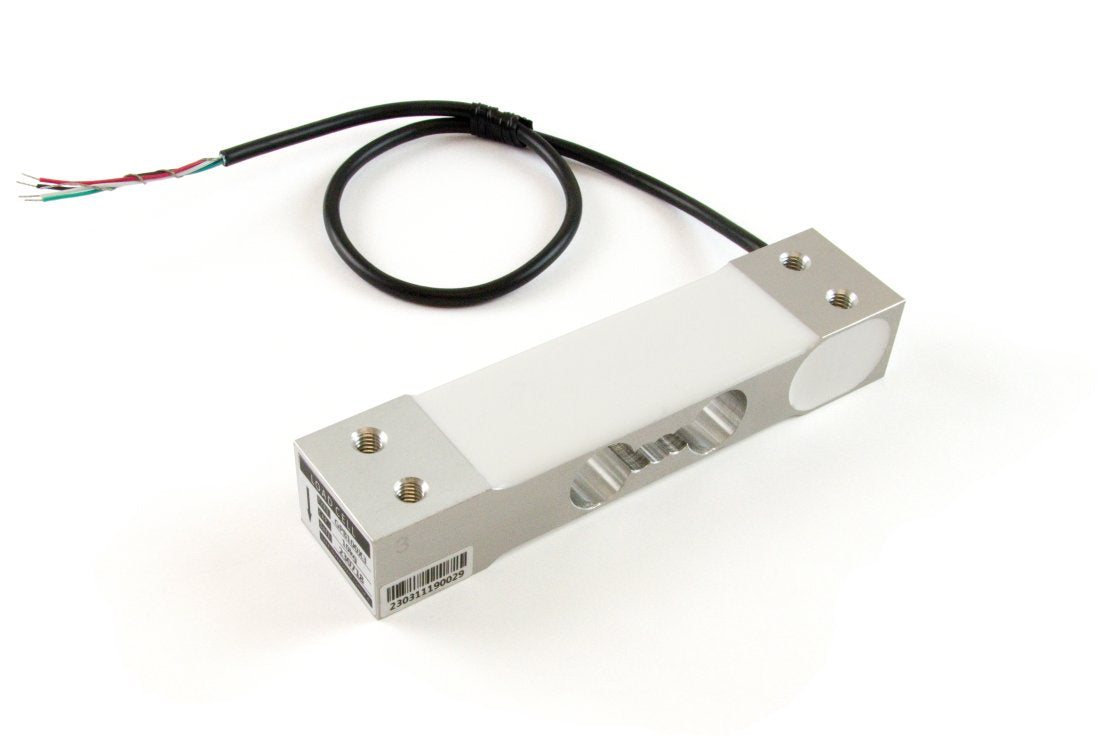
Measuring weight or force is essential across industrial automation and product testing: from dosing scales and material tension testers to tank level monitors and quality control rigs. To bring physical weight data into software, you need two core elements — the right load cell for your mechanical structure, and a bridge interface to amplify and digitize those tiny electrical changes. Pick the right combination and converting raw force into pounds, kilograms, or Newtons becomes a simple, calibrated linear equation in your code.
Why you can't read a load cell directly with a standard microcontroller
A strain gauge load cell outputs a minuscule voltage signal — typically measured in millivolts per volt (mV/V) or nanovolts per volt (nV/V). Standard analog-to-digital converters (ADCs) on typical microcontrollers or USB boards simply lack the resolution and low-noise amplification required to detect these microvolt shifts. A specialized load cell interface (such as the Wheatstone Bridge Phidget) supplies stable excitation voltage to the sensor, amplifies the output signal, and uses a high-resolution 24-bit ADC to output a clean, stable digital reading straight over USB or VINT.
The four main load cell types
1. Single-point load cells — versatile platform weighing
Single-point (or binocular) load cells feature machined cutouts in an aluminum beam that bend predictably under load. They are the go-to choice for small-to-medium weighing platforms and bench scales (up to ~50 kg). Their primary advantage is off-center compensation: an object placed anywhere on the platform yields an accurate weight reading. One end mounts to the rigid base, and the other mounts directly to the weighing platter. A controller paired with a compact Single Point Load Cell (50kg) provides a straightforward solution for custom bench scales.
2. S-type load cells — tension and hanging loads
Named for their "S" shape, these sensors excel at measuring tensile forces (pulling) up to 500 kg or more, though they can handle compression as well. Typically installed using eye bolts or rod-end bearings, S-type load cells are standard for crane scales, cable/wire tension testing, structural suspension monitoring, and automated material strength testing. Sensors such as the Steel S-Type Load Cell (500kg C3) offer high-grade C3 accuracy for heavy-duty hanging measurements.
3. Platform & shear beam load cells — heavy multi-point platforms
Designed for large industrial scales, livestock scales, and tank weighing systems, shear beam and platform load cells are built to operate in parallel. Combining multiple load cells at the corners of a frame allows you to support heavy, dynamic loads exceeding 500 kg while maintaining structural stability and precision.
4. Button load cells — high capacity in tight spaces
Button load cells (or load buttons) are low-profile, cylindrical sensors designed purely for compressive force in space-constrained environments. Featuring a raised contact button on top, they handle high capacities (up to 1,000 kg or more) where traditional beam sensors cannot fit physically.
Quick comparison
| Load Cell Type | Primary Force | Typical Capacity | Best For | Key Advantage |
|---|---|---|---|---|
| Single-Point | Compression / Bending | Up to 50 kg | Bench scales, dosing pumps | Off-center load immunity |
| S-Type | Tension & Compression | Up to 500 kg | Hanging scales, cable tension | Easy eye-bolt attachment |
| Platform / Shear Beam | Compression | 500 kg+ | Multi-point floor scales, tanks | Parallel array integration |
| Button | Compression | Up to 1,000 kg | Compact assemblies, press fit | Ultra-compact footprint |
How to choose — three questions
- What direction is the force applied? Pushing downward on a platter → Single-Point or Button. Pulling or hanging → S-Type. Large multi-corner frame → Platform/Shear Beam set.
- What total weight and accuracy class do you require? Select a capacity rated above your expected peak load (including tare weight). Check the accuracy class (C3 or C4 offer sub-0.025% total error for high precision).
- How many sensors and what sampling rate do you need? A single-channel Wheatstone Bridge Phidget (like the DAQ1500_0) handles 2 inputs over VINT, while dedicated multi-input boards (like the PhidgetBridge 4-Input 1046_1) support up to 4 sensors with higher data rates over USB.
Wiring and calibration workflow
-
Wire the color channels: Standard 4-wire strain gauge load cells connect as follows:
- Red: VCC / 5V (Excitation power)
- Black: Ground (GND)
- Green: + Signal (+ Output)
- White: - Signal (- Output)
- Connect to your interface: Secure the wires into the terminal block of your Phidget Wheatstone Bridge controller using a 2mm screwdriver.
- Read raw V/V output: In software, read the unitless ratio (V/V or mV/V) provided by the 24-bit ADC channel.
-
Perform a 2-point calibration:
- Record the raw V/V value with no load (Offset / Tare).
- Place a known reference weight on the scale and record the new raw V/V value (Gain / Slope).
- Apply the linear formula in your code:
Weight = (RawValue - Offset) * Gain.
Practical tips
- Mount to rigid surfaces. Any mechanical flex in your mounting brackets will absorb force and cause measurement errors or drift.
- Check directional arrows. Most beam load cells have an arrow stamped on the side indicating the correct force vector direction.
- Avoid thermal expansion stress. Temperature changes can cause metals to expand. Allow the system to warm up and zero (tare) your scale periodically in software.
- Never overload the sensor. Dynamic impacts (dropping an object onto a scale) can exceed the rated limit instantly. Select a sensor capacity with a safety factor of 1.5x to 2x your maximum anticipated load.
Wrap-up
Integrating weight measurement into software comes down to selecting the right physical load cell form factor for your mechanism and pairing it with a high-resolution bridge interface. Wire the 4-wire bridge correctly, perform a quick 2-point calibration, and your code can measure weight, tension, or force with high precision and reliability.
Need help choosing the right load cell + interface pair?
Tell us your load capacity, mounting space, and accuracy targets — we'll recommend the ideal load cell form factor, Phidgets interface board, and wiring hardware. Genuine products, local stock, and fast delivery.
Plan your weighing setup →